
Flared port testing part three
Determining inner flare requirements
Aims
Flares control turbulence by allowing the airstream to expand in a controlled fashion.
For the flare on the inside of the box, this process occurs as the air flows into the box.
On the alternate half cycle, where the air is flowing out of the box, the inside flare is compressing the air,
causing it to be well behaved, even for small flares
This set of tests is designed to examine the hypothesis that the inside flare can be made smaller because
it's turbulence will be masked by the inrush of air. If this is found to be the case,
a mathematical relationship will be developed
Method
A fixed sized outside flare will be coupled with a
series of smaller inside flares and their performance measured.
The technique will be the same as used in earlier tests, and will be done using 86mm diameter ports.
The existing ports will be cut and rejoined to make the various sizes required.
Selection of flare sizes
The following graph shows the results found in earlier testing of 86mm diameter ports.
For these new tests, the maximum velocity, as shown by the green line,
will be kept below the core limit.
The outside flare will be chosen from above the line, and the inside flares will be all those that lie beneath the line.
This arrangement means that the only audible noise will come from the inside flares
The light grey sloping line is what we are hoping to see from our inside flares
This gives the following ports, all having the same 300mm effective length
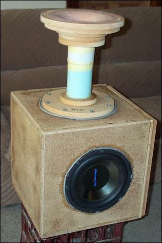
The 35mm rejoined port being tested
Results
See the raw data (Round3) for actual measurements at the different frequencies
The following table summarises the relevant results:
For ease of analysis, the results for each frequency have been graphed separately. The vertical scale is in m/sec.
The black crosses are the new measurements, showing how each flare performs when fitted to the inside of the box.
The colored line and the lighter crosses are from the earlier tests, and show how the same flare performs when fitted to the outside.
If more performance can be extracted from a flare when it is fitted to the inside of the box,
we would expect the black crosses become significantly higher than their colored counterparts as area ratio is increased. This would stop as the core limit "plateau" is approached
The 15hz figures suggest a possible improvement for the 25mm and 35mm flares. The 50mm flare shows no improvement
Similar results for 20hz
The 25hz figures are much the same except the result for the 50mm flare is above the core limit, and is thus in error.
A better value for this flare is shown by the light grey cross.
The 30hz figures suggest a possible improvement for the 25mm and 35mm flares, although quite small
The 35hz figures suggest a possible improvement for the 25mm flare only.
There is no result for the 50mm flare because of insufficient power in the test equipment
Conclusion
There appears to be a small amount of improvement for the 25mm and 35mm flares.
This would suggest that for the popular flares in the 20mm to 35mm range, the inside flare could be reduced by around 5mm.
Larger flares, which operate up near the core limit, don't show any improvement.
Putting this into more general terms:
For speeds below 70% of the core limit, the radius of the inside flare can be
15 - 20% smaller than that of the outside flare