Custom built Port Flares
To get a flare radius of 35mm or more the Heated PVC over a mold method fails
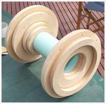
A custom flare can be made by adding MDF rings to the outside of PVC pipe and using a profiled scraper to shape the flare with automotive body filler

Cross section of a large custom flare

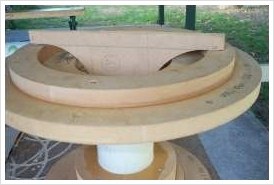
50mm flares before the body filler is added

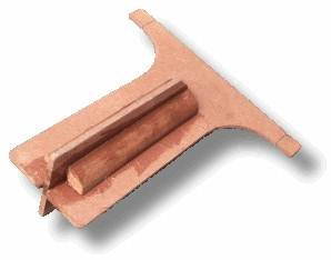
A scraper is made from some thin sheet...

and then slid into the port and rotated to shape the body filler into the flare
This technique was used to produce large flared ports for turbulence testing at up to 31 m/sec. One disadvantage of this method is that you need a new scraper for each flare radius. Here's the eight made for the tests:

In normal use, port compression considerations will force you to design for a lower velocity,
where turbulence can be dealt with using flares smaller than these. However some require large flares
when designing car subwoofers for SPL competitions.
As it happens, I've helped someone out in this area, and the design is perfect to illustrate
the maths...
Example of maths for large custom Flare
I received an email recently asking for help from someone who wanted to build a huge flare for SPL competitions. He asked for a 100mm radius flare on a 180mm diameter port. I'll use his request to illustrate the maths
Assume the port is to be made from 5mm thick PVC tubing with an inside diameter of 180mm and an outside diameter of 190mm

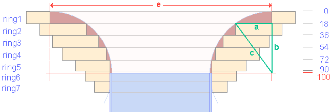
Cross section of a large custom flare
Step1 - Check dimensions
Decide on the thickness of MDF or other timber you are making the rings from. In this case it was 18mm
Step2 - Make a drawing like that shown above
Work out how many rings are needed. Here we need 7 rings to produce a 100mm flare.
The last ring is to give enough surface area to bond to the PVC tube.
Once the bodyfiller is added, a flare of this size will weigh a fair bit!
Mark the drawing with the distance each ring is from the outside face of the flare as shown above in
blue
Step3 - Work out the inside diameter of each ring
For each ring, work out dimension "a" as follows:
As an example, the green triangle is used to work out the value for ring2.
c = radius of flare
c = 100mm
b = 100 - 18
b = 82
From pythagorus' theorem
c^2 = a^2 + b^2
re-arranging terms gives:
a = sqr(c^2 - b^2)
a = sqr(100^2 - 82^2)
a = sqr(10000-6724)
a = sqr(3276)
a = 57
The inside diameter of each ring is dimension "e" minus twice the value for "a"
As you can see from the drawing, dimension "e" equals the inside diameter of the port plus twice the flare radius,
in this example 380mm.
Working all the rings out with the same method gives:
| dimension a | id of ring | notes | |
| ring1 | 0 | 380 | |
| ring2 | 57 | 266 | |
| ring3 | 77 | 226 | |
| ring4 | 89 | 202 | |
| ring5 | 190 | same as OD of port | |
| ring6 | 190 | same as OD of port | |
| ring7 | 190 | same as OD of port |
Step4 - Work out the outside diameter of each ring
When gluing the rings together, I like an overlap of 30mm.
This is achieved by making the OD of each ring equal to the ID of the next larger ring plus 60mm.
The outermost ring has to double as a mounting flange, so it should have an extra 30mm all round in addition to the overlap.
In this example, the two smallest rings can be the same size.
Putting all this in a table gives:
| Inside diameter | Outside diameter | |
| ring1 | 380 | 500 |
| ring2 | 266 | 440 |
| ring3 | 226 | 326 |
| ring4 | 202 | 286 |
| ring5 | 190 | 262 |
| ring6 | 190 | 250 |
| ring7 | 190 | 250 |
All that remains is to cut the rings and glue together. Once they are dry, glue the PVC into position. Referring to the drawing, we can see that for this example, the PVC tube is positioned so that 10mm of ring6 is visible from outside the port.
Quick tip
After gluing the rings together, use a sharp knife to bevel the inside edge. This allows the bodyfiller some depth and prevents the edge of the rings showing through in the final product
