
QRDude Build
The time has come to build some QRD diffusers ...
The location of these is described on the Home Theatre tips page.
It was decided to build three N13+4 diffusers, each being 1200mm high, 500mm wide and 150mm deep,
made of 3mm luan ply over a core of styrofoam, weighing in at at around 7kg.
Here is the design...
N13+4 diffuser
Build style
Most builds are done using a backboard, which is the easiest option, but I was keen to see what the challenges would be in building without one. This requires the maximum depth wells to use the same width floor plates as the other wells, as shown in the third option below. For the fins to hold this plate, they need to be 150mm deep. This method relies on the top and bottom endplates to provide the strength for the maximum depth wells.
Cutting
The diffusers will be cut from sheets 2400mm * 1200mm, and be 1200mm high overall.
Subtracting the thickness of the endplates gives a length of 1194mm for both the fins and the floor plates.
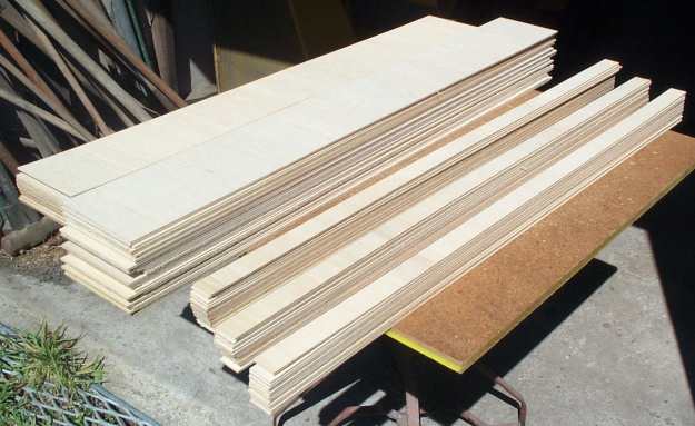
Since the plywood supplier has a much better saw than mine, I'm getting them to cut the strips.
An extra fin will be ordered for each diffuser to be cut in half for the top and bottom plates.
Two extra floor plates will be ordered for each diffuser to be cut up to make stiffening braces if needed.
The guys at Mr Plywood
rewarded me for sticking to only two sizes, doing a very good deal on the cutting charges.
Parts list
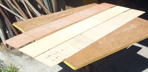
4 sheets of 3mm luan ply 1200 * 2400
- trim sheets down from 1200 to 1194
- cut 45 strips 150mm wide
- cut 45 strips 35mm wide
- any leftover wider than 700, cut lengthwise down the middle (to fit in my little grey volkswagen...)
- I should have checked out which way the grain ran - cutting the sheets in half first and turning 90 degrees
before cutting the strips would have looked better.
Adding styrofoam to the mix
After talking to Terrry Jones, it seems that the ply may need more support, so there will be some polystyrene foam used
under the floor plates to keep everything square. In fact, building without a backboard would be a nightmare
if not for the foam!
It turned out to be easiest to pre-build smaller sets of wells first, and then join these together later on.
The build...
Here is the anticipated sequence...
- Glue 10mm and 25mm thick sheets of polystyrene together to get 35mm thickness to match well widths
- Cut polystyrene into strips to go under the floor plates. Width of strip equals QRDude block height
- Sand the edges of all strips
- Glue floor plates to polystyrene strips
- For each diffuser, cut spare fin in half to use as top and bottom plate
- Glue Fins and floor assemblies together in the right sequence, along with top and bottom plates
- Trim endplates to length.
- Give the diffusers 3 coats of polyurethane using a one inch brush.
The back face of the ply is not consistent in color and quality like the front face. Luckilly, there aren't too many sheets with the darker timber or stained areas. These faces will be hidden by using them either side of the shallowest wells.
Ply was not exactly 3mm thick - closer to 3.6mm - Will not matter for well depth as this can be compensated for when cutting the styrofoam packing. The overall with of the diffusers will be slightly larger than the planned 500mm, but in the intended location, this will be OK.
Working with the styrofoam
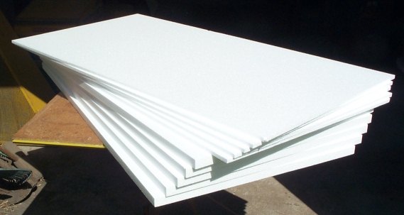
Polystyrene sheets in the exact thickness to suit the well width were not available, but combining two
thicknesses gives the correct size.
These were found at
Insulation Industries
for not a lot of money...
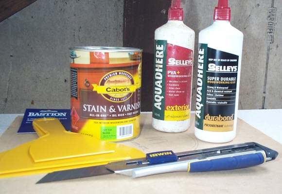
Glue selection for joining the two sheets together is tricky. Normal PVA glue needs access to timber grain and / or air to cure. Contact cement can contain solvents that dissolve the polystyrene. A Google search recommends Aquadhere Durabond (Gorilla glue), which doesn't contain solvents, and cures using moisture. The glue was spread onto one sheet with a plaster scraper, whilst the other sheet was wiped over with a damp cloth to activate the glue. The two sheets are clamped overnight...
Once the glue proved to be OK, the rest of the sheets were done the next day. Took nearly the whole 460ml bottle of glue. (Coverage 3.6m^2)
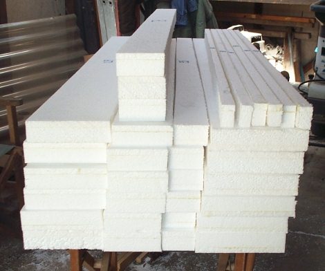
Cutting the 35mm thick combined polystyrene needs a long sharp blade, so a snap-off knife was purchased. To get an even coverage with stain, an all-in-one stain+poly product was also bought...
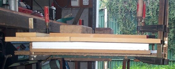
The new knife tended to tear the styrofoam a bit, and was hard work, so a fine saw blade was liberated from a mitre saw. This gave a smoother cut, and could shave quite a fine amount, as was needed to trim the 1200mm sheets by 6mm.
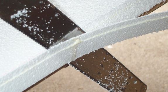
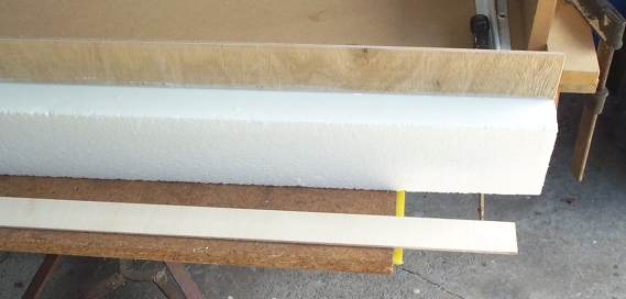
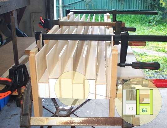
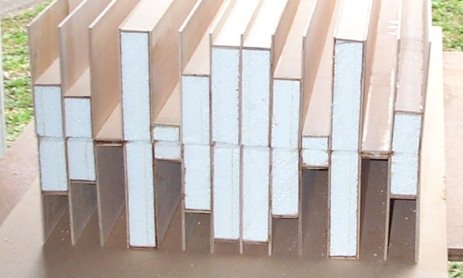
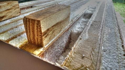
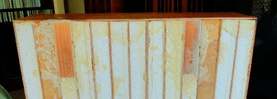
Unfortunately this approach made it impossible to cut at 90 degrees, as can be seen by the different directions of leaning in this sneak peek at the relative heights of the wells
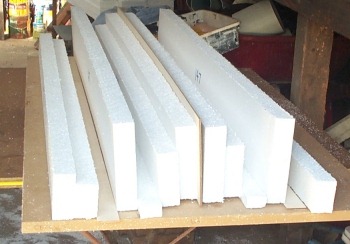
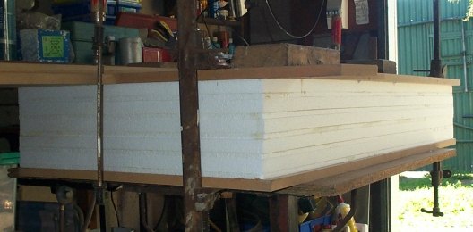
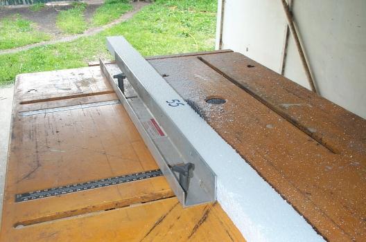
The saw table was wheeled out, and the edge that will support the well bottoms was trimmed square. For each set of same sized pieces, the saw was set to skim the smallest piece. The remaining pieces were then fed through, giving the same height. Some shims will be needed under the styro during assembly, to compensate for the loss in block height.
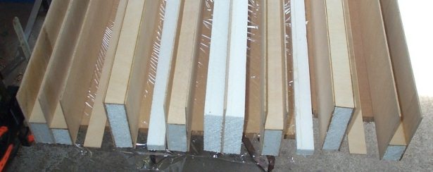
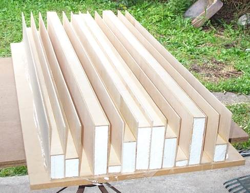
Here are all the pieces ready for gluing to the ply
Building smaller sections first
Whilst the original plan was to first glue all the floor plates to the foam, it was going to be a pain to keep the styro in line,
as it had inherited a slight bend from the earlier gluing being done on a surface that was bowed. D'oh!
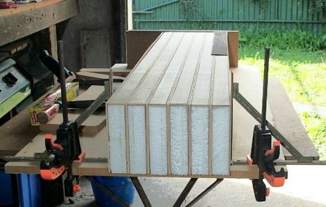
The solution was to build a jig that would hold six equal-sized wells at once,
keeping them square and aligned.
The fins and floor plates for each well would be glued onto the foam block for that well. The wells would
not be glued to each other, and after drying, would be separated for later assembly into their correct positions
in the three diffusers. The jig holds six blocks of foam and twelve fins.
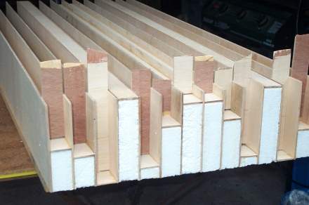
Here is the test-fit of all the zero-depth wells, for the three diffusers. Angle brackets hold them upright,
whilst an end-stop keeps all the components in line. Sitting on top is the set square that was used to position
the end-stop when it was clamped.
Setting up the jig
Deciding how to break up the build
The colors in the next drawing show four different sets, each of six wells. (a pair from each of the three diffusers)
The blue set will require temporary packing whilst in the jig, using an additional nine fins, so it needs to be done before
all the fins are used up. Its floor plates will be added at final assembly time.
Four sets of equal block heights
Because there is no backboard, and no rebated endplates to hold the fins in place, it will be much easier to assemble
the diffuser from these pre-built blocks than to try and glue everything from scratch in one session.
Before starting, it is worth grading all the fins so that defects on the back side of the ply can be hidden by facing
that side into the foam. Put the worst fins against the shallowest wells (ie the one with the most foam).
The best floor plates also go with the shallowest wells.
Here is one of the sets ready for gluing, (the 55mm ones in the drawing above)
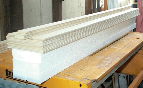
The pieces for one set
With the deeper wells, it's not possible to get the glue nozzle all the way down to where the floor plate will sit,
so the right order of assembly had to be thought out...
Firstly, some sandwich plastic is laid down on the work surface to stop the glue from sticking to it.
Next a zig-zag bead of glue is put onto one side then spread with a brush to give full coverage...
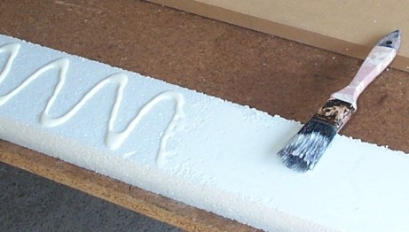
Full coverage with the glue
The fin is added, then the glue applied for the floor plate. An extra bead of glue is laid along the seam where the floor plate will touch the fin...
Floor plate about to go on
With the floor plate on, the glue can be applied for the second fin. Again an extra bead of glue is run next to the exposed edge of the floor plate, and then brushed onto the edge. The second fin can then be added, and the assembly dropped into the jig for alignment.
Glue applied for second fin
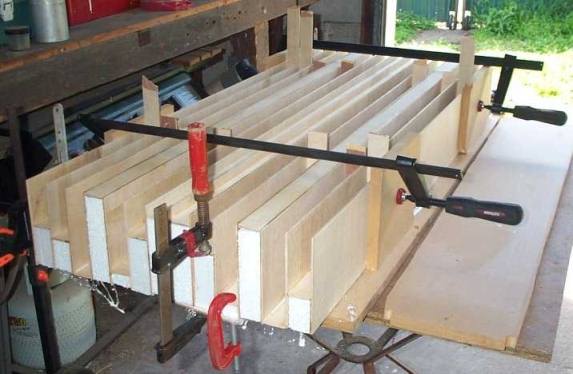
When the entire set is glued up, clamps are used to hold everything parallel. (not so tight as to crush the foam). Leave for 24 hrs.
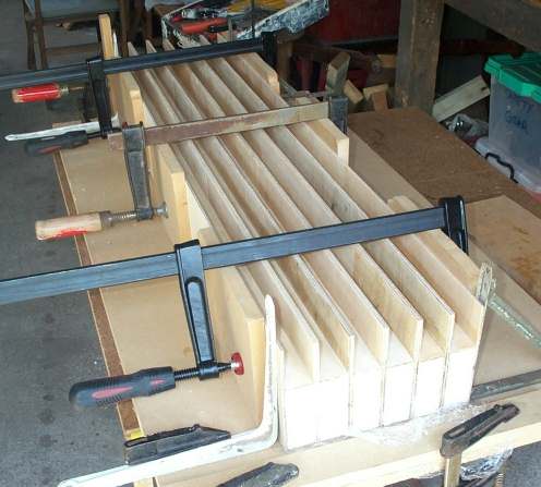
One of the sets drying
Once the four sets are finished, the same jig can be used to glue the LHS end wells for the three diffusers onto three of the wells from the 55mm set. This step means that all fins are held upright by at least one block before the final assembly begins. The final three fin-sized pieces, that are yet to be cut in half for the endplates, will first do duty as packers for this step.
Supporting the lone end fins
Gluing the sections together
The sets arranged for gluing to make one of the diffusers
Now we're getting there
Sets glued together. The smaller clamps in the foreground were used to pull a warped floorplate into line.
Those new clamps were definitely needed
Some spare floor plates were broken up and used as packers during clamping.
Packers in place for gluing and clamping
The packers hadn't been thought of when building the sets, or assembling the first diffuser. Here is the first one sitting on top of the second one. You can see that the fins on the right end aren't quite at the proper angle. Not a huge problem here, but definitely something to watch out for if you opt for this build method.
First diffuser wasn't packed
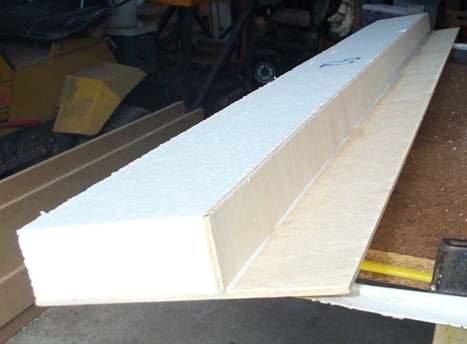
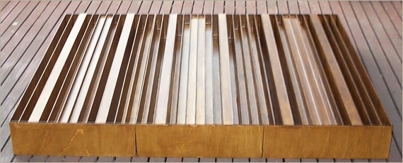
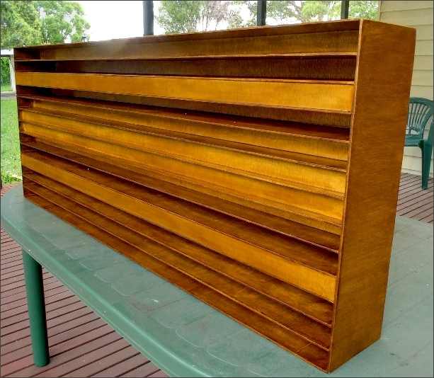
Finally, a look at how they turn out...(just the endplates to go)
First look
Carefully stood up...and then turned around. The plastic will come off now to give the residual glue a chance to dry.
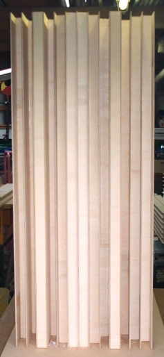
Another look
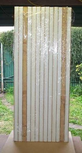
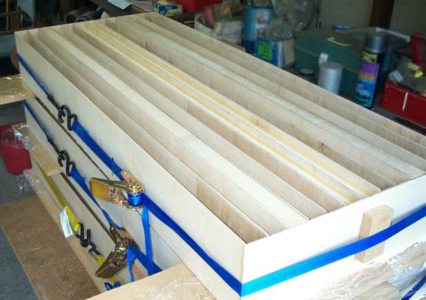
Tie-down straps used for gluing all the endplates
A plastic drinking straw taped to the glue nozzle allows the deep wells to be sealed.
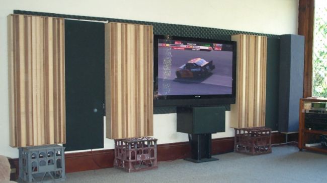
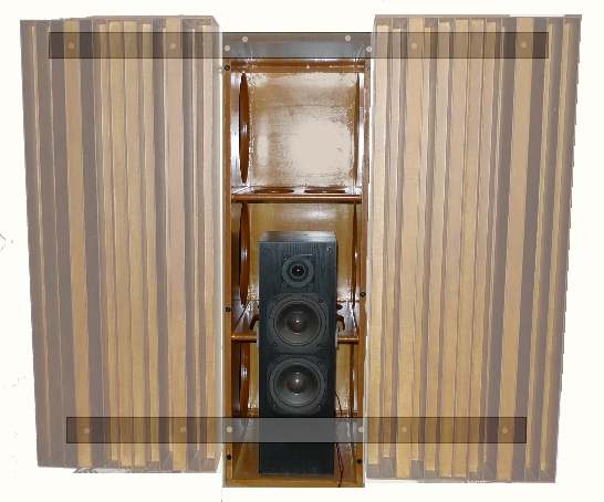
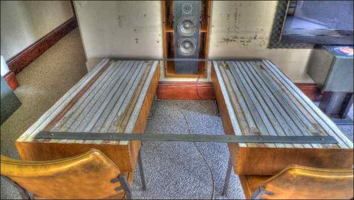
Where they will go...
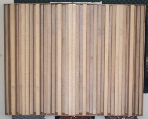
How three periods look if they are mounted together...
Stained
Stained and finished with low-sheen poly
Mounting
The original intention was to use brackets mounted to the wall using expanding plug screws. The diffusers were to push over the brackets, deforming the styrofoam, giving a firm flush mount.
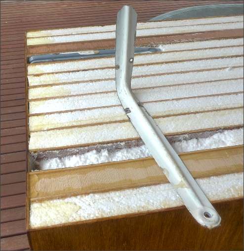
Foam was carved out from the back of the zero-depth wells to accept trimmed-down brackets
Unfortunately, the lath-plaster walls of the house weren't strong enough to take mounting plugs for the brackets, so a new approach was needed. Flat steel plates were mounted across the IB manifolds, behind the grilles. Wooden blocks glued into the back of the zero-depth wells allow the diffusers to be mounted using screws through the plates.
Mounting plates
Mounting block about to be glued in flush with back of diffuser panel
Blocks in place
Steel straps
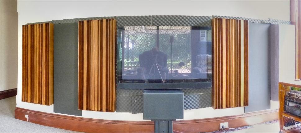
Finally mounted
Cost in Aussie dollars (2010)
| Plywood, cut into strips, including $22 cutting charge for 90 strips | 110 |
| Polystyrene sheets 1200mm*600mm - 5 @ 10mm, 5 @ 25mm | 36 |
| Glue to join styro sheets and to bond mounting blocks - Aquadhere Durabond (US equivalent is Gorilla glue), two 460ml bottles | 48 |
| Glue for ply - Aquadhere Exterior (US equivalent is Titebond II), nine 500ml bottles | 135 |
| Polyurethane with Stain - Cabots all in one New Teak gloss, two 1litre tins | 88 |
| Polyurethane - Cabots low sheen, one 1litre tin | 26 |
| Plastic plaster scraper (to spread glue on styro) | 3 |
| Sandpaper | 10 |
| Flat steel plate for mounting 50mm * 3mm * 6m | 25 |
| ----- | |
| Total for 3 diffusers | $481 |
Extra glue had to be bought several times during the build - Buying the 4 litre size for $56 at the start would have saved $64
Lessons learned
- Use thicker endplates. Route slots in them to accept the fins and the well bottoms.
- Glueing the ply to the styrofoam used a huge amount of glue. Do away with the styrofoam and build them face down. This puts the glue on the back where it is not visible. Use temporary blocks keep the well bottoms flat during glueing.
- Apply the stain / clear or whatever before cutting the sheets. Touch up after cutting. This means normal PVA cant soak into the grain, so go for something like Gorrilla glue (Aquadhere Durabond here in Australia). A low-sheen finish doesn't show the gluelines like a gloss finish does.
- The 3mm luan ply was nice and rigid - more so than MDF would be, however the quality of the back of the ply is not as good as the front, so some alternative would be worth looking for.
- Glue some blocks behind the shallow wells to provide hidden hardpoints for mounting